Sunday, 23 October 2011

Technical Drawings


Model


The model was constructed from plastic RHS section and balsa wood.

The Final Concept Drawing

Concept Development 3

The final stage of the development was the sourcing of the dimensions of the stainless steel section from my supplier. After going through the range of RHS and the varying wall thicknesses and the suitable size of 50x 25mm with a wall thickness 1.6mm was selected. This meant that the radius of the corners would be 25mm and a section of pipe would also be needed.

The image shows the front section of the chair with the radius corners


The image above shows how the chair would be constructed through the cross sections. The front section of the chair required a 'V' shape section of material to run across the front face to keep the face flush.
The rear legs have the same on the back face for the same purpose. With the timber housings welded to the reverse sides.

Concept Development 2

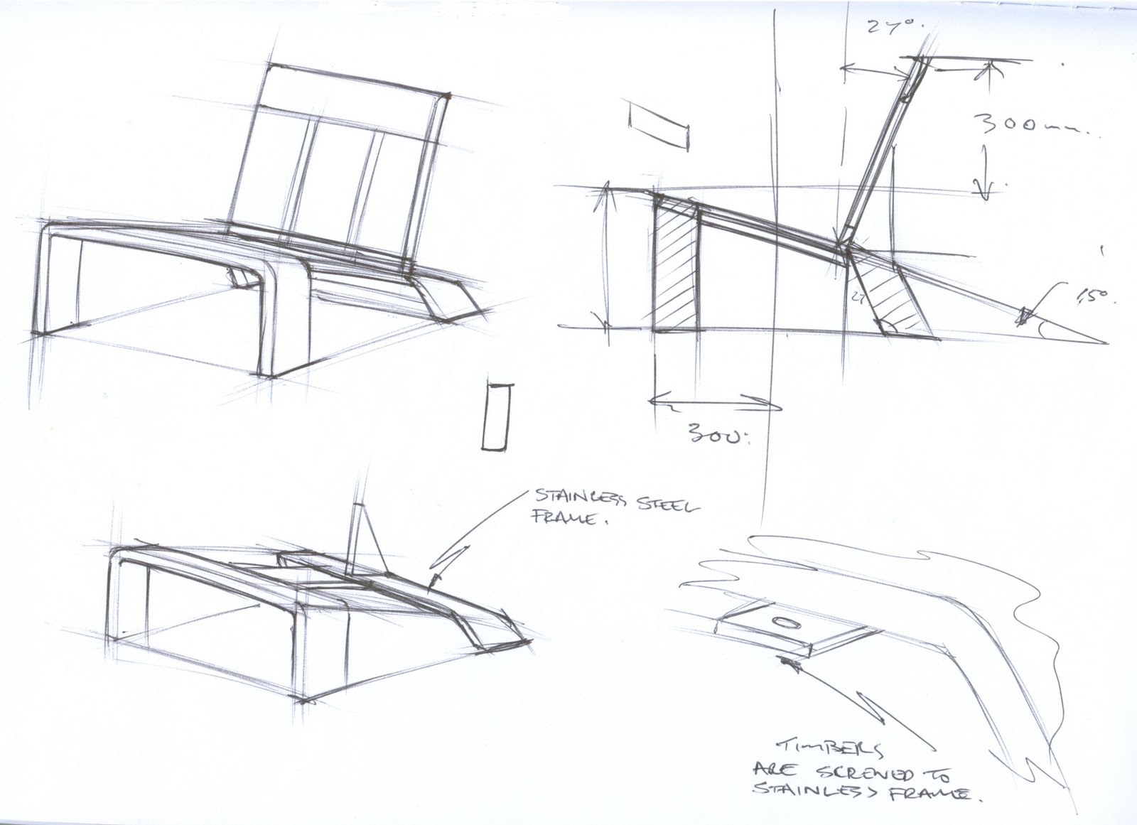
The second stage of the development was to measure the modified chair for dimensions and to redevelop the design with regard to the new dimensions.

This image shows the initial idea and the basic idea of the size and the basis of the frame and the timber connections.


This second image shows the alternate idea of construction for the chair.


This final image shows the final concept of the construction of the chair, with the timber able to slot into the holes cut in the timber.

Concept Development

After consultation, I decided to develop concept 4.

The main issues that needed to be developed were the size of the materials that would be used in the production of the concept, the seating position and the fabrication methods which would be used to construct it.

As a result of the seating position issue and starting with a bar stool as inspiration, I needed to source another chair to modify to find the seating position I found suitable for my design.


This chair provided an ability to be modified to find the required seating position due to the round bar frame as it is easily cut, bent and welded due to the malleability of the section.


The rear legs were cut 50mm below the seat of the chair and were pressed back until the fresh cut met the seat of the chair and welded into place. this provided a more relaxed seating position for the user, while this chair was still usable the rear legs of the new chair would need to run back further than that of the back rest.